Figure 2. NOGAnaut PC board traces and parts layout.
The NOGAnaut is constructed "dead-bug" or "ugly-style." Unlike most kits with which you may be familiar, there are no holes to poke the component leads through the PC board. In this project, all components are soldered onto the same side of the board as the circuit traces. This is similar to "surface-mount construction" with which you may be familiar (there was a series of articles in QST, winter-spring 1999, on surface-mount construction if you are interested).
The reason this type of construction was chosen for this project is simple: it makes it much, much easier to make modifications to the circuit in the future. This kit is meant as a starting place for you to make your own modifications, and experimentation. Unsoldering components mounted through a PC board is much more difficult-in fact, the better made the PC board, the harder it can be to remove components (some "plated-through" boards make it down right impossible to remove components).
Looking at the PC board (see Figure 2), you will see that most of the board's surface is a ground plane. However, "islands" have been cut out of the board to provide places to solder circuit connection points together.
Notice also in Figure 2 that C1, C2 and C4 are shown with two capacitors, one slightly grayed out. In order to achieve the necessary capacitance for these circuit components, you may have to parallel two capacitors. For example, if you don't have a 750-pF capactor for C4, you can parallel a 680-pF and a 68-pF capacitor. There are other combinations as well, using standard value capacitors, such as 470-pF and 330-pF, 560-pF and 180-pF, etc. If you have a second capacitor, place it where the grayed-out component is shown in Figure 2.
Figure 2. NOGAnaut PC board traces and parts layout. |
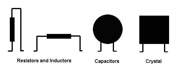
There are several ways to mount a part onto to the circuit board. The easiest is to cut the component leads to approximately ½ inch, and then bend a very small part (about 1/16th to 1/8th of an inch) of the end of each lead perpendicular to the lead. For some components (such as resistors), you may have to bend one of the leads parallel to the part to fit neatly on the board. This is where you get to make decisions about how you want your board to look when you're done. Some suggestions are shown in Figure 3.
 Figure 3. Some suggestions on how to mount parts onto the PC board. |
Use a pencil soldering iron (say between 25 and 45 watts or so) to build the circuit. To solder a component lead to the board, first touch the tip of the iron to the place on the board where you wish to place the lead. After briefly heating the board, apply a small amount of solder, to make a small blob on the board. Put the solder down, pick the part up by the other lead with needle-nosed pliers and place the lead that you wish to solder to the board on top of the blob you just made. Then reapply heat touching the blob with the iron long enough to remelt the solder around the bent component lead. Finally, grab the lead with your needle nose pliers for about 20-30 seconds, to dissipate some of the heat away from the part.
This may take some practice--you can practice by soldering small pieces of component lead anywhere you'd like on the ground plane (the big open area covering most of the outer part of the board). Clip them off when you're done practicing-it is, after all "ugly" construction! It's not hard, once you get used to it.
Once you install the first lead of a component, installing the other lead(s) is easy-just apply a small amount of heat and solder to the appropriate place where the lead contacts the board, melt enough solder to hold it in place and remove the heat. Again, grab the lead with needle-nosed pliers for 20 or 30 seconds to help draw off excess heat and avoid damaging the component.
You can install the components in any order that you wish, however, we've found the following order of installation to be simple and straightforward.
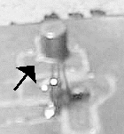
 Figure 4. The 2N2222A transistor mounted on the PC board using "ugly construction." |
Copyright ©, 1999, Mike Boatright, KO4WX (Copies may be freely made with attribution)